
We were asked by Snap Chat to be an early developer for there new Snap Chat Lens Studio. So we decided to make this chill Zen Shapehead.
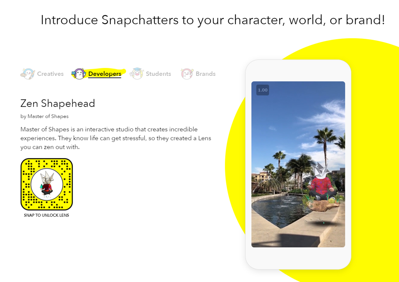
Essentially the new tool Snap Lens Studio is like a simplified Unity and it makes it quite easy and user friendly to make an AR “lens”
The character was modeled, textured and animated in our 3d program of choice then exported as FBX where you then relink the textures and animations and add some simple logic even sounds in Snap Lens Studio. Its easy to push to your phone for testing because they have a built in wifi pairing. The last step in the process was making the snap icon which was just as fun as making the AR filter itself.
And here it is out in the wild:
Go ahead and check it out for yourselves with this link or snap code above
Try out Zen Shapehead AR Lens
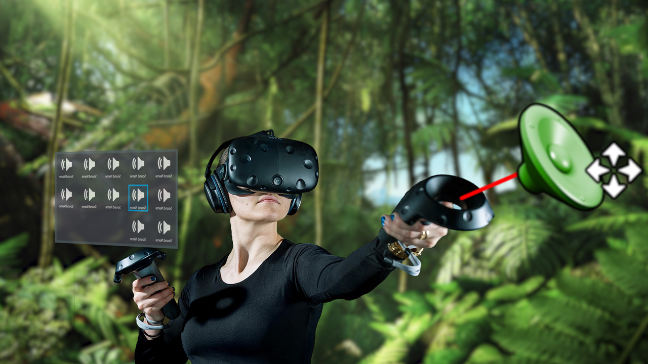
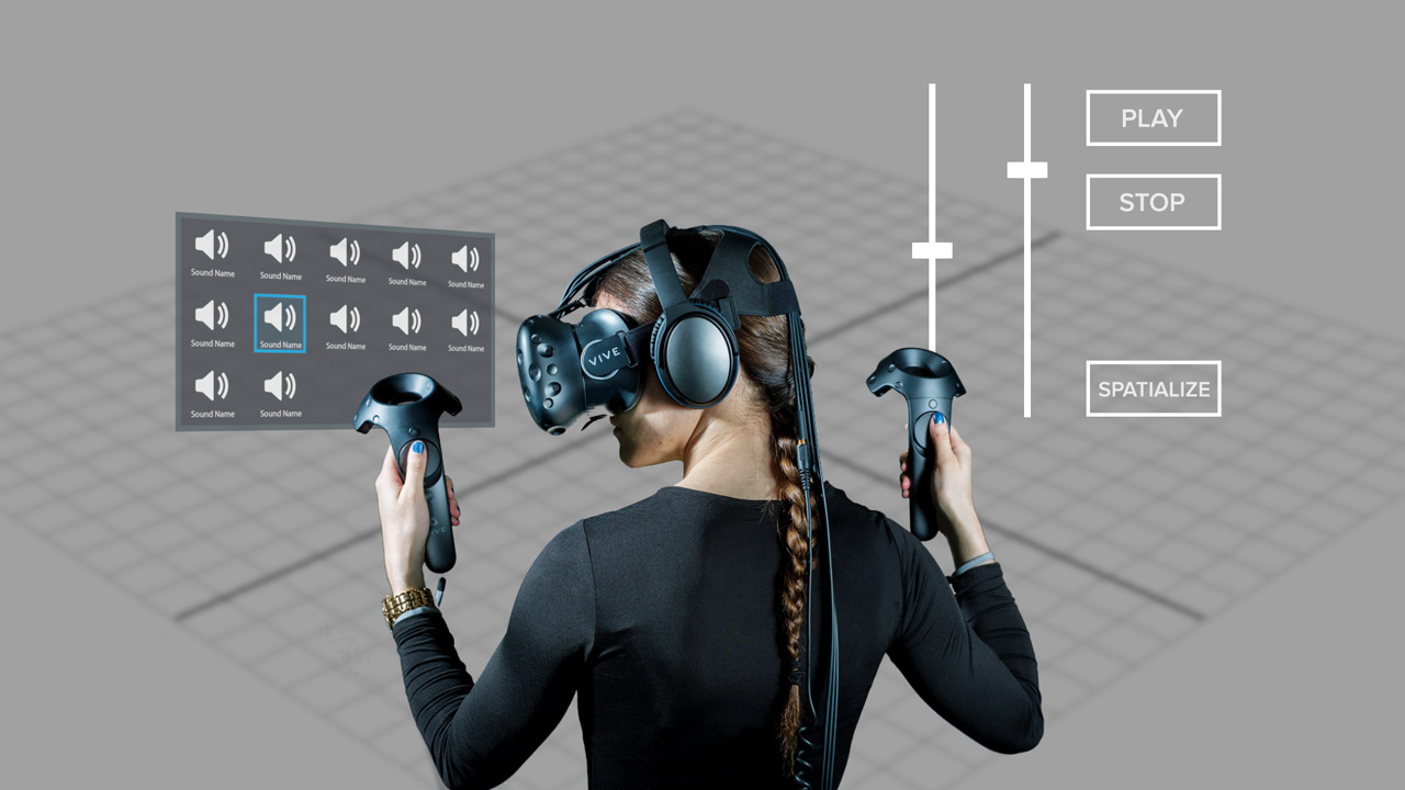
A simple tool that lets you place, edit and spatialize sound in VR
Posted on October 19, 2017 by Adam Amaral
We were asked by Intel to create a useful tool for VR devs that leverages the power of intel CPU’s. Unreal Engine has a powerful virtual reality editor option, but something they did not include is the ability to edit and place sounds while inside VR. It can be troublesome constantly having to restart the editor after adjusting a sound to test what it sounds like in VR. So we decided to create a sound editor that allows game devs and sound designers alike to quickly place, edit, and test spatialized sound inside VR! This will prevent the user from having to constantly enter and exit the editor.
Requires:
-Unreal engine 4.18.1 or greater
-Visual Studio 2017
-HTC Vive
What you’ll learn:
-Motion Controller interaction
-How to create custom C++ class
-VR UI
-Saving editor changes
-Sound spatialization parameters
Below is a step by step tutorial outlining the details of how we made this from start to finish:
After you have downloaded and unzipped the project folder, you will have to do a couple of things to get started. We’re assuming you have at least version 4.18.1 of Unreal Engine installed.
First, right click on Intel_VR_Audio_Tools.uproject and select Generate Visual Studio project files. After that completes open the project. A popup that says “Missing Intel_VR_Audio_Tools Modules” will appear. Click Yes to start the rebuild, this should take less than 20 seconds. This is needed because of how we are dynamically finding .wav files that have been added to the project, which will be explained in the Custom C++ Class section.
Setting up VR player:
We started with Unreal’s Virtual Reality template and chose the MotionControllerPawn as our pawn which has motion control setup and allows movement by teleporting.
Motion Controller Interaction:
Before the motion controller can interact with 3D widgets a Widget Interaction component needs to be added to BP_MotionController, which is located in the VirtualRealityBP folder. Also added was a scene component for the sound selector widget, called soundScene.

Press and Release Pointer keys were attached to the event called when right trigger is pulled. This was added to the MotionControllerPawn also located VirtualRealityBP.

Custom C++ Class:
The reason you had to rebuild the project was because early during the making of this tutorial the issue of knowing the names and locations of the sounds and dynamically updating a widget to match all those files sounded daunting. Luckily, Unreal Engine has some stuff to help us out.
The IntelSoundComponent is a C++ class that can be added to any blueprint for an easy way to dynamically locate and load a .wav file into a USoundWave which is how Unreal loads a sound file.
First, we had to right click in the content browser and create a new C++ class which we named IntelSoundComponent. This action created an IntelSoundComponent.cpp file and an IntelSoundComponent.h file.
Next, we added some includes which are needed to locate and manage files.
Includes added in IntelSoundComponent.cpp are Paths.h, FileManager.h and Runtime/Engine/Classes/Sound/SoundWave.h (which for some reason needed everything before SoundWave.h).
Image (IntelSoundComponent.cpp)
We began by creating a bool named exists, 2 FString variables named dir and SoundDir and a TArray of FStrings named soundFiles. Since soundFiles is a TArray we are able to call soundFiles.Empty(); which empties the TArray. We believe it’s also the fastest way if new wave files are added. Then, we set FString dir to FPaths::ProjectDir();(which gives the root location of the project). Now, we set FString soundDir to dir + “Content/Sounds” because that is the folder we are putting our .wav files into. FPaths has another method that can check if a directory exists so we set our bool to that .(exists = FPaths::DirectoryExists(soundDir);)
Image (IntelSoundComponent.cpp)
On Begin Play we start by instantiating IFileManager by using IFileManager &fileManager = IFileManager::Get();. This was done to debug and test if the wave files were being found with fileManager.FindFiles which are searching for .uassets instead of the .wav files we were using before as .uassets are more reliable when sharing projects.
Image (IntelSoundComponent.cpp)
Lastly in the .cpp, we create two functions that will be exposed as blueprint nodes. SoundArray which passes the soundFiles TArray into blueprints and setWavToSoundWave which honestly took a while to figure out because we had to find a way to dynamically reference a .wav file in a way which Unreal could understand which is a USoundWave. For this problem we discovered LoadObject
In the IntelSoundComponent.h we created two UFUNCTIONS as a way to make the two functions in the .cpp blueprint callable.
Image (IntelSoundComponent.h)
Blueprint function to expose sound files into blueprint.

Blueprint function passing a wav converted in USoundwave into blueprint.

Setting up UI:
Three UMG widgets we need to create

Create the blueprints needed to manage those UMG widgets

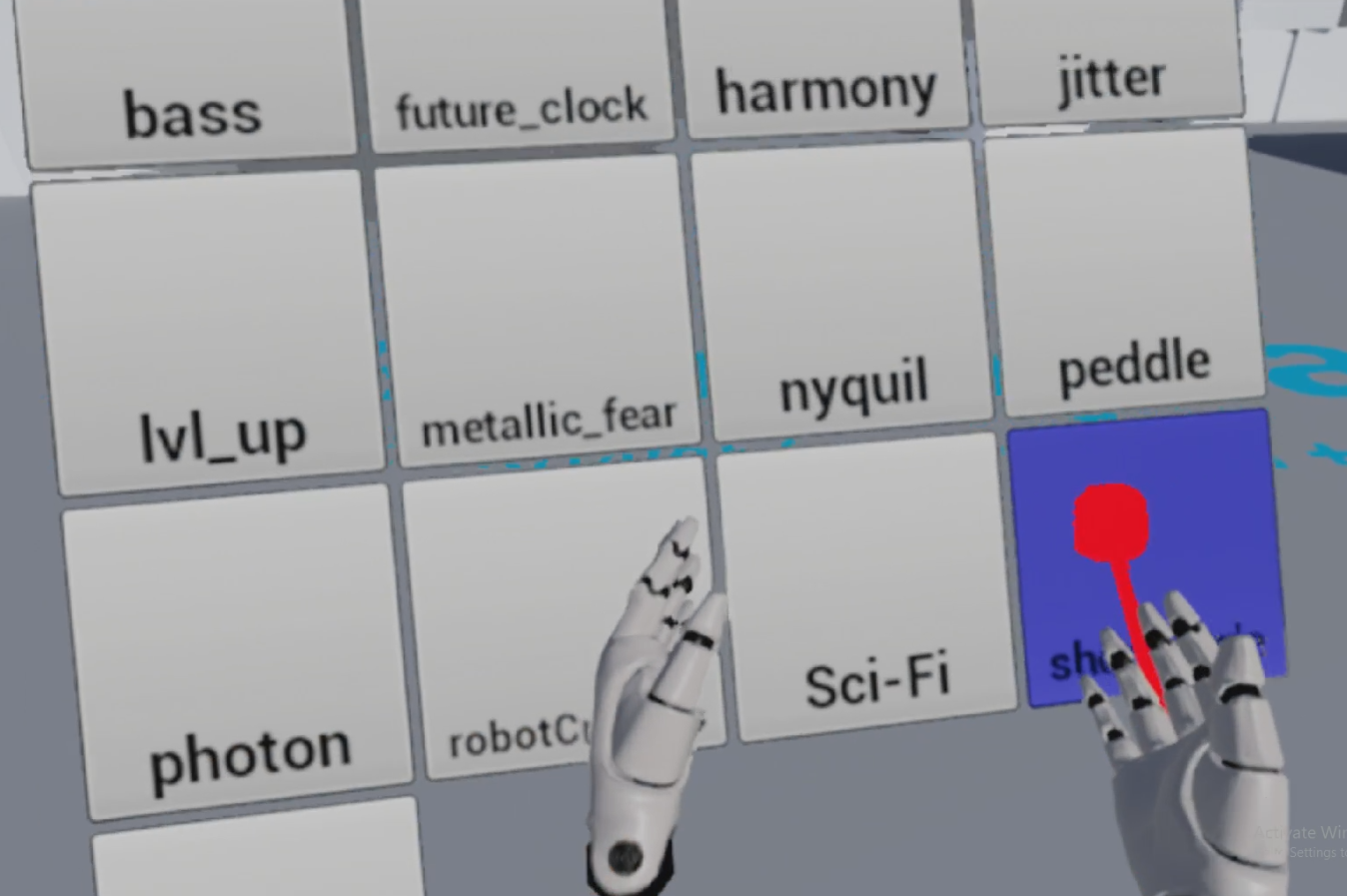
We have a couple of widgets for this project. AudioParamsSliderWidget is the widget that pops up when you select a sound. soundButtonWidgetBP is just a button widget for the sounds in the Content/Sounds folder. soundSelectorWidgetBP is the widget, which i put in the level by having an actorBP we created called IntelSoundWidgetBP (you could do this dynamically but then you would have to get a reference to the newly spawned actor everytime you began play.), gets the sounds from the SoundArray C++ node and populates soundSelectorWidgetBP with soundButtonWidgetBPs. All this happens in the IntelSoundManagerBP which was also placed in the level from the start.
Image (IntelSoundManagerBP)
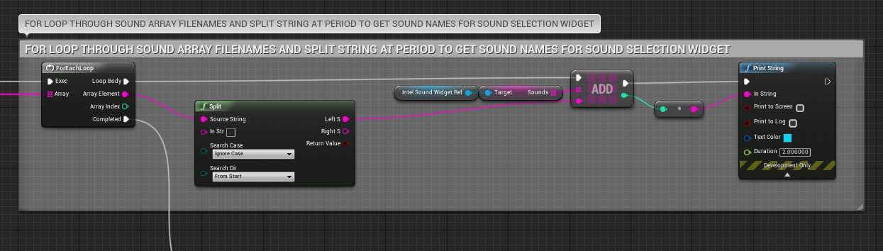
In the image above we get the soundFiles TArray of FStrings and split at the period in the name of the (name of sound).wav. We send that string into an array of strings in IntelSoundWidget to name the buttons being dynamically populated.
Image (IntelSoundWidgetBP)

In the IntelSoundWidgetBP we spawn the soundUI,
add sounds,
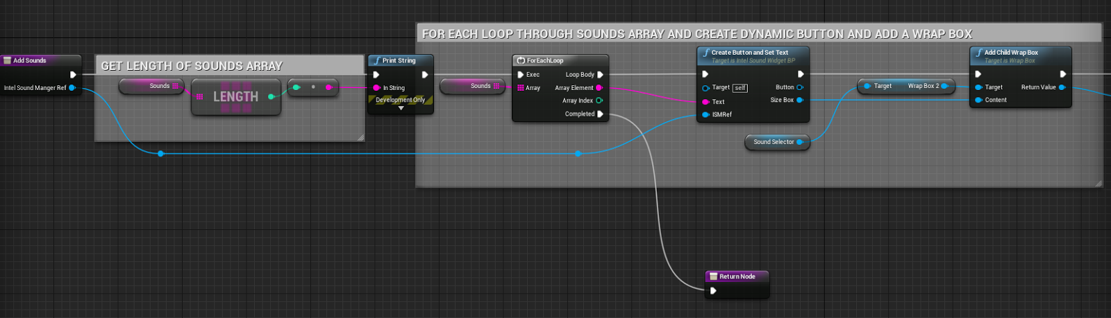
and if we didn’t use the Set Widget node the widget would spawn but not be visible in game.
Sound Parameters:
Once the player selects a sound from the widget. An IntelSoundAudioActorBP actor will spawn. In this actor you will see the AudioParamsSliderWidgetBP and if Spatialize? is clicked 3 attenuation settings exposed to be changed through the widget..

Sound Attenuation is essentially the ability of a sound to lower in volume as the player moves away from it.

The 3 settings exposed are Attenuation Function, Attenuation Shape and the Falloff Distance.
There are plenty more settings that could be exposed with more time. Here are images of the Attenuation Setting struct in Unreal.
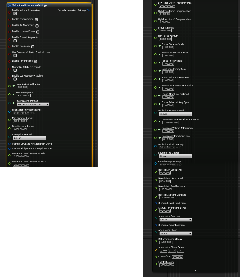
We believe the 3 we chose are the most basic and fundamentally needed settings. Showing debug lines when you are changing settings is something we are working on. We were looking for a way we could use the attenuation setting debug lines Unreal uses to show attenuation in editor in game, but we have not found that answer. So, we might get the shape extents of the attenuation shape and function chosen and use Unreal built in draw debug lines nodes.
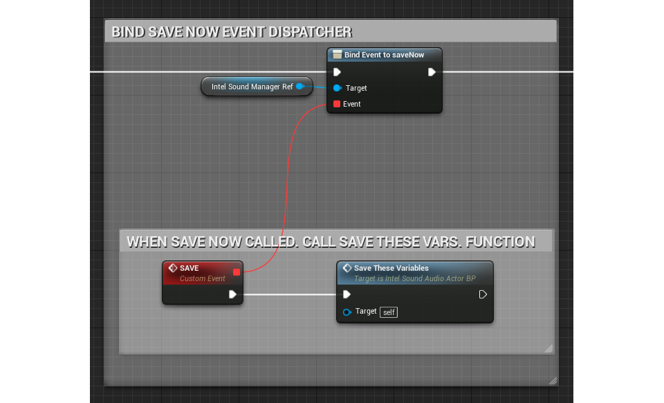
Saving on Exit:
When you exit the game and have spawned sounds, moved them around and played with the audio parameters we save all the variables we believe are important using IntelSaveGameBP through IntelSoundAudioActorBP.
Image (IntelSaveGameBP)

Image (IntelSoundManagerBP)
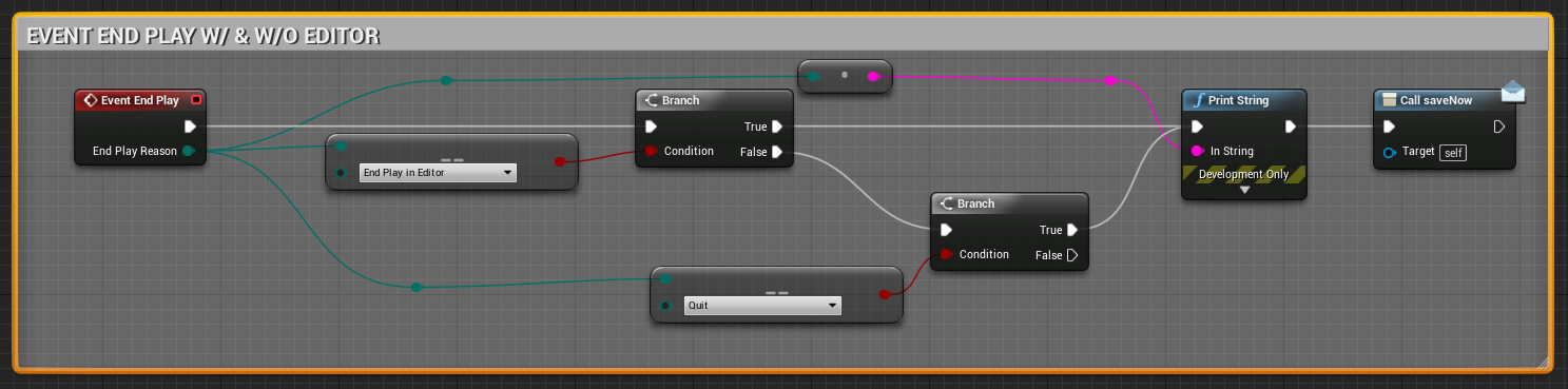
Image (IntelSoundAudioActorBP)
Now if everything worked correct you should be able to edit any sounds in your folder inside VR.
Tutorial written and developed by Rob Meza

All the fun none of the fumes
Posted on April 19, 2017 by Adam Amaral
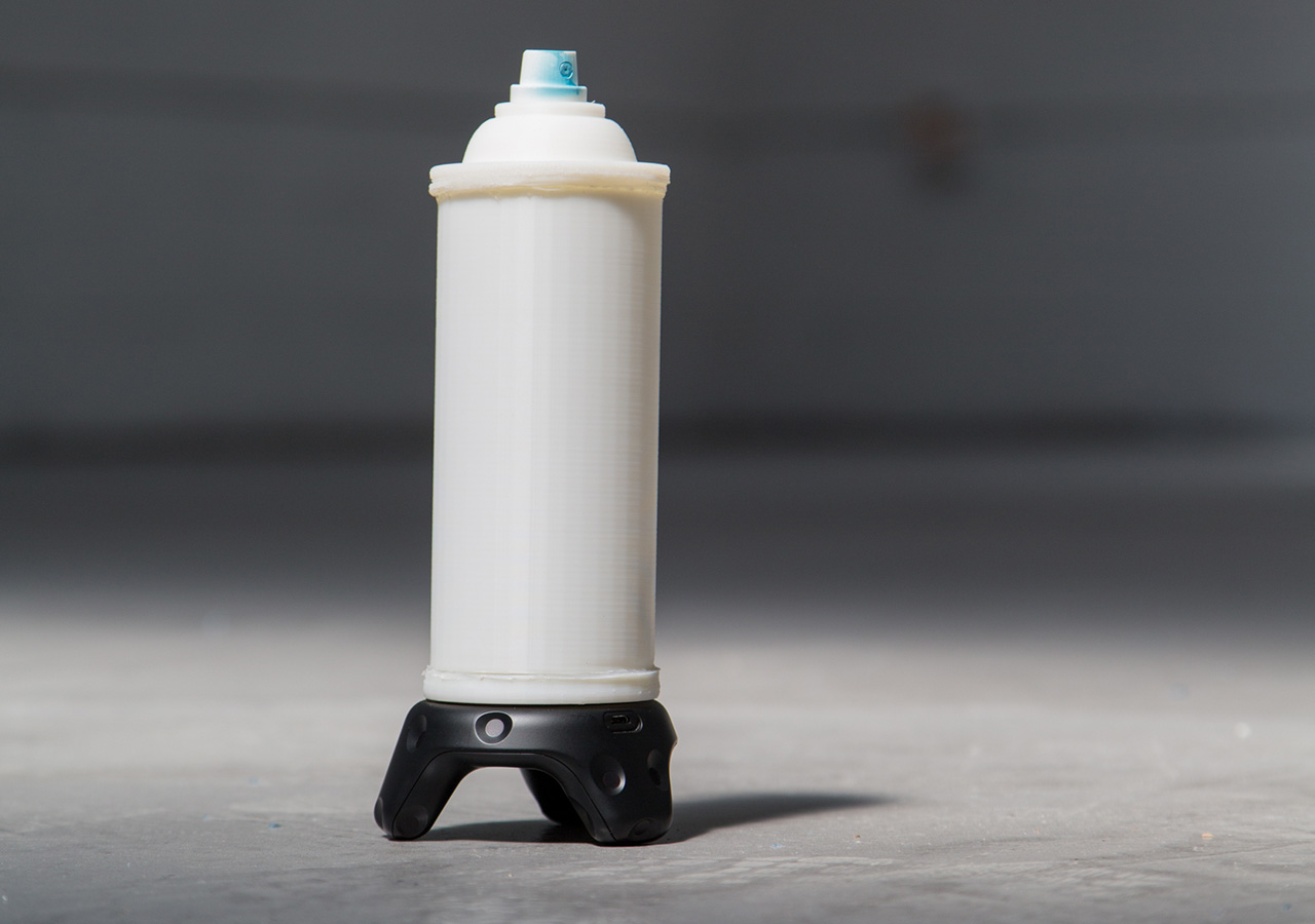
After working on the first-person-shooter-oriented Mobile Room-Scale, we wanted to make show off the more creative side of VIVE Tracker. For this, we developed a 3D-printed spray paint can that uses the GPIO pins on the VIVE Tracker to send commands to a demo game we’ve created in UE4.
In this tutorial, we will teach you how we did it. We’ll give you the print files needed, walk you through assembling the physical model once it has finished printing, and show you how to connect the incoming signals from the VIVE Tracker Spray Can into the demo game in UE4.
Part 1: Making the Controller
What you’ll need:
Tools
- -3D Printer
- -Solder tools
- -Hot glue gun
- -Wire Cutters
- -Small flathead or other tiny pry tool
Parts List:
- -VIVE Tracker
- -¼ inch attachment for VIVE Tracker
- -Print files
- -spray nozzle/cap from spray paint can
- –Scale up and scale down buttons
- -trigger button
- –22 gauge UL wire – solid
- –jumper cables female-female
Step 1: Print the models
Print Files Folder
Step 2: Assemble the Can
Full Assemble Can Video
Steps:
- 1) Print the 3D files
- 2) Remove the plastic shield from one side of 6 of the jumper pins
- 3) Take the jumper you are going to use for the ground and cut off the other shield
- 4) Strip the head of that jumper
- 5) Cut 1.5 inches from 4 other jumpers, keeping the shield on one end
- 6) Strip those wires and solder them to the ground cable to make a 4:1 ground jumper
- 7) Insert one of the exposed heads of each of the 6 jumpers into each of the holeson the printed base
- 8) Make sure the metal head sticks out about 1mm
- 9) Use the hot glue gun to lay hot glue into the rectangle to hold the jumpers in place
- 10) Fix the jumper heads into the correct position as the hot glue dries
- 11) Use the 1/4 in attachment to fasten the base to the tracker
- 12) Solder 3 inch of lead red and black wire to the scale up and scale down buttons
- 13) Strip 1⁄2 inch from the other end of the wires
- 14) Feed them through the holes on the cylinder and hot glue the buttons into the grooves
- 15) Solder 2.5 inches of green and black lead wire to the trigger button and feed the wire down the top of the cap. Use hot glue to fill the hole available.
- 16) Feed the female sides of the jumper cables attached to the base through the tunnel on the cylinder
- 17) Once fed through you can plug the buttons in. The up button will go to pin 3, the trigger to pin 4, and the down button to pin 6.
- 18) Line up the tunnel to the opposite of the pins on the base
- 19) Align the notches, and twist the cylinder into place, locking it to the base
- 20) Align the notched on the cap to the cylinder, twist, and lock the cap in place
- 21) Take the nozzle from the spray can and push it onto the top button
Part 2: Making the Game
What you’ll need:
For this tutorial, you will need the FBX file for the entire spray can along with the project files for the game we are building. The game is already finished, and the blueprints have all been extensively commented to let you know why we’re doing what we’re doing.
Spray Can: FBX Model
Spray Can: UE4 Project Files
Preface:
Since the VIVE Tracker has just come out, some of the programs we are using haven’t quite caught up to fully incorporating their functionality as of this tutorial. As such, we have a few workarounds to hold you over in the meantime. Once everyone has updated to the OpenVR version that fully supports the Trackers these workarounds won’t be needed.
The first thing you will need to do is download and use the VIVE Tracker Role Changer (VTRC). As of this tutorial, version 0.8 was the newest. Here is the LINK. That allows us to use the GPIO pins as controls when sending to programs, like UE4, that have not updated to the new version of OpenVR just yet.
Here are a few things we think you should be looking out for while we wait for the update to OpenVR:
- -Pairing the Tracker as the second device before using the VTRC will result in the
controller inputs coming in on the wrong hands. Example: Tracker location shows up as
LEFT controller but is triggering RIGHT inputs. - -If, for unexplainable reasons, the Trackers stops registering in UE4, try to restart
SteamVR. In most cases this solved the issue (we believe it is not closing the secondary
data connection when the game closes) and we were able to get back up and running
quickly. - -If the Tracker still does not show up, rebooting your machine should do it.
- -The Trackpad input (pin 5) currently does not register in UE4 with OpenVR.
Step 1: Setting up UE4 for the Motion Controllers
Full Motion Control Setup Video
Steps:
- 1) Create pawn blueprint
- 2) Add scene component
- 3) Add a camera to the scene component
- 4) Add a motion controller component for the left controller to the camera component
- 5) Add any static mesh to the controller component (I’m using a box I scaled down)
- 6) Add another motion controller component for the spray can
- 7) Set that Motion Controller Hand to Right
- 8) Add a scene component to the spray can motion controller, this will be tracker
- 9) Add the spray can mesh and an arrow component so you can see the spray direction
- 10) I set the arrow’s Z position to 180 and Z rotation to 270, which is right at the location of the spray can’s tip
- 11) I set this scene component’s X location to -12 to compensate for the tracker’s size and overall feel in the game.
- 12) I also rotate the scene component Rotation X & Z to -90 because the spray can’s movement did not feel right.
Step 2: Create the Controls for the Inputs
Full Create Controls Video
This section is built to follow within the Project as there are many parts to its operation. Please open the project files for even more detail on this build out.
Below is a summary of what to look for within the Project files:
- – Open the VR Pawn blueprint
- -Go to the Event Graph
- -On event begin play the tracking origin and color for the cube on the second controller are set
- -On event tick we are getting the valid tracked device ID of the controller type, the Tracker should come in as a controller after using VTRC
- -Since we are always connecting the tracker first, we’ll get the first valid ID and set the world location and rotation of the scene1 root of the can mesh
- -The second valid ID will do the same for the color cube on the left motion controller
- -The trigger will be used to change the boolean for “spraying”
- -The grip button will increase the size of the nozzle
- -The menu button currently comes in as the shoulder event. We will use that to decrease the nozzle size
- -On event tick we are checking if the “spraying” boolean is true
- -If it is we call the function line trace/set wall and paint ref
Outside of VR
More fun can be had even outside of VR. For example combined with a projector you can have all the fun of graffiti without the fumes.
Multiplayer cross platform VR
Posted on April 19, 2017 by Adam Amaral
We debuted our first multiplayer mobile room scale experience at CES this year, and we were actually quite surprised to see how many people actually had alot of fun playing our game “Cover Me!!”. Quick background: “Cover Me!!” is a cross-platform multi-player experience where a person plays in VR alongside his friends who use their cellphone or tablet to blast away waves of enemies. I know what your thinking… “typical wave-based shooter yada yada” BUT by using Vive trackers and attaching them to your cell phone or tablet you have full room-scale tracking ability just like the Vive system. Throw in a few Bluetooth guns and next thing you know you’re shooting laser blasters back-to-back with your buddy in VR, fully aware of each other in the game and working as a team. For us, this solved the problem of going over to a friend’s house and watching them having the time of their lives while you sit on the couch waiting your turn. Now you can play along with them!
Since Vive trackers are available to the public, we thought we’d share how to make a mobile room-scale experience. This could be done in Unity or Unreal Engine, but in this specific tutorial We’ll be showing you in Unreal Engine 4.15. Difficulty: intermediate
Replicating tracker positions
![]()
One thing to know about the VIVE Tracker is that while they were designed and produced by Vive, the core tracking technology comes from SteamVR (Valve). The trackers use a proprietary Bluetooth connection that requires SteamVR to be running. Currently SteamVR does not run on ARM processors which most(all) phones use. To solve this, we need to replicate the position of the trackers from the VR computer to the other mobile players. Sounds kind of rough but honestly isn’t that bad and over a local network there is no noticeable latency.
If this is your first time building a multiplayer game I highly recommend checking out this tutorial: Blueprint Multiplayer Shootout Game and having a good understanding of replication and how it works inside of UE4. From there let’s handle sending position to the other players.
![]()
As you can see in the image above it’s a fairly simple setup. We’re identifying if the player is a VR player or Tracker Player (this is stored when player joins game) then we check if this event is happening on the Server or on a remote client (switch has authority node). Notice the custom events being called on tick (red). They are slightly different and this is important. Since we know we can only get position values from a tracker on the PC running SteamVR we only want that PC setting our variables and then broadcasting over the network. We do this by setting “Execute on Server” this prevent us accidentally setting the tracker position variable on a device that doesn’t even have Steam VR running.
![]()
We use the built in “Get Tracked Devices Position and Orientation” node using the index of the tracker. We know its id “5” in this case because we are assuming we have base stations (0 & 1), HMD (2), Left and Right controllers (3&4) making the two trackers connect (5 & 6). You could add additional logic here but for sake of example we hard coded.
Once you have this setup and working locally now it’s time to package your game for android and PC. Start your PC server first then it should be straightforward to connect mobile devices as long as you’re on the same network. One “gotcha” to look out for, that Unreal by default assumes you’re not going to be connecting over LAN, to force this edit your “DefaultEngine.ini” file located in your projects config folder by adding the following anywhere in the file:
[OnlineSubsystem]
DefaultPlatformService=Null
Hope this helped and let us know if you run into any issues.
HTC Vive Tracker + Google Daydream VR
Posted on February 17, 2017 by Adam Amaral
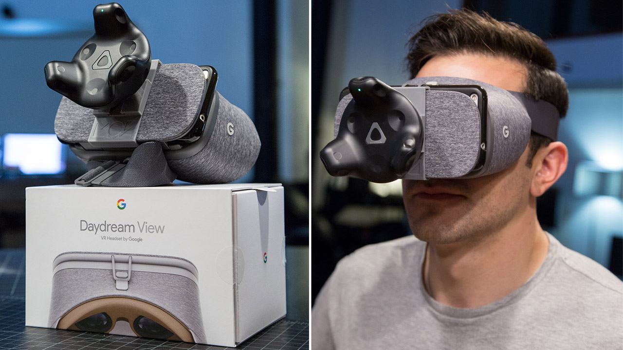
We are big fans of the new HTC Vive tracker and have been lucky to have early developer access. At CES we used the trackers for our mobile room scale experience “Cover Me!!” , which allows players to use their mobile devices along side a VR teammate. But we see alot more potential for the trackers… One thing that has been on our minds as of late is the Google Daydream Headset and I have to say its pretty solid. While it doesn’t match the tracking capabilities or graphics of a desktop HTC Vive experience the Daydream is wireless and the pixel resolution is a good bit higher (1440×1280 px per eye). Now wouldn’t it be awesome if you could have the room scale tracking ability of the Vive with the wireless higher res Daydream….? To the lab!!!
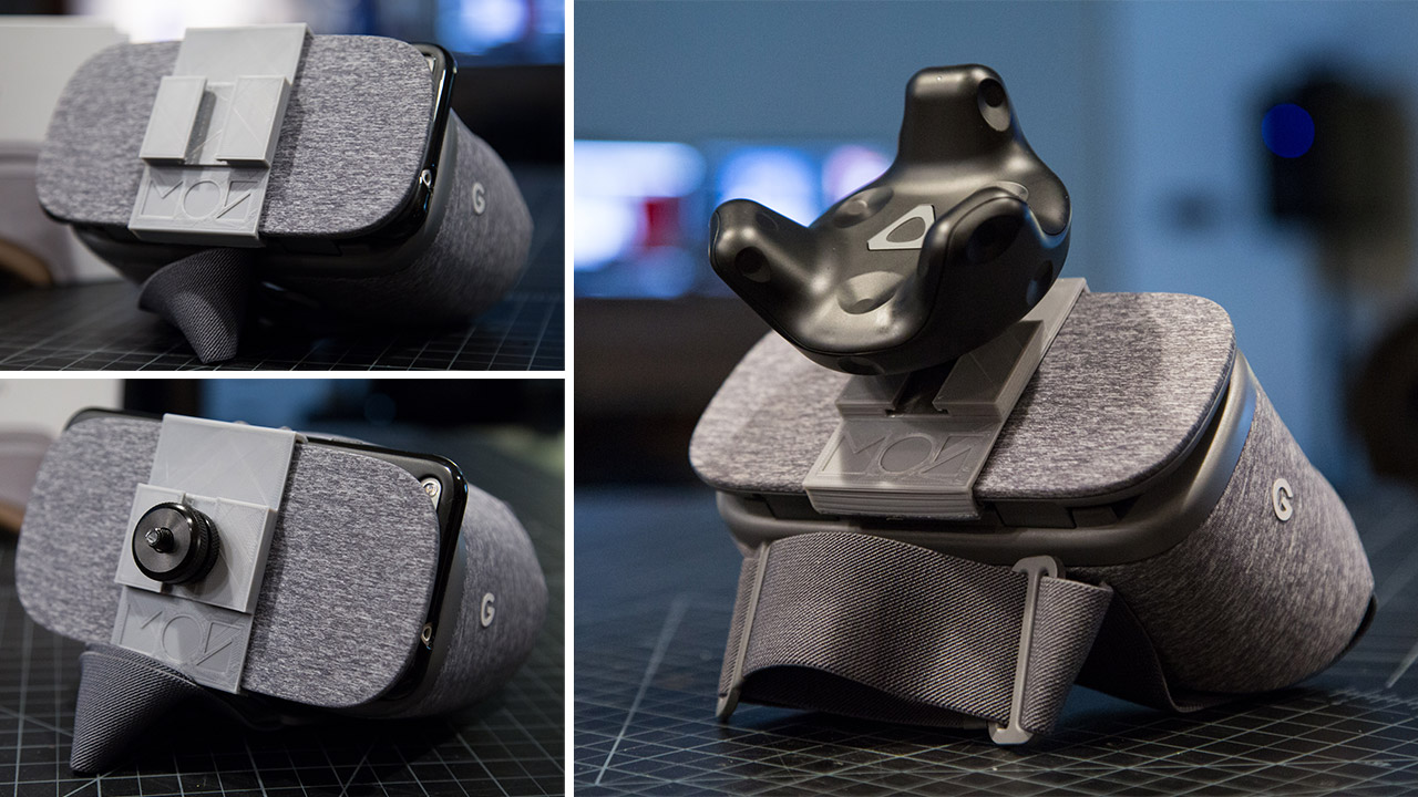
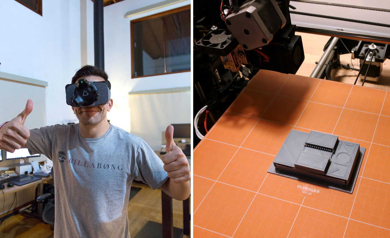
Combining the Vive Tracker with Google Daydream seemed like a perfect combo. From our previous experience with the Vive trackers we have already solved how to stream their position data to android devices so the only next step was designing a way to hold it on the Daydream. We contemplated creating a head strap to mount on top of your head but for sake of quickness we decided to just mount directly to the Daydream with a custom 3d mount. (this might change revision 2) Our trusty 3d printer came in handy, a quick model in 3d software of choice followed by a lucky first try fit and we were in business. The Vive Tracker has a universal tripod mount on the back so using that in combination with a tripod hot shoe for dslr camera’s gave us a snug strong fit.
Now I’m sure your wondering but is it as good as the Vive? In short, NO…. its hard to compete with tracked hand controllers, desktop graphics and a wider field of view so Vive is still the winner here. But!! I will say the daydream with added room scale is pretty awesome. There is something really cool about having no tether and sharper resolution. The big downside for now is that there aren’t any room scale games for Daydream (minus ours I guess) so we just ran a demo of our game “Cover Me!” modified to support the tracker and new headset. In the future I could really see this expanding (we aren’t finished yet!)
Excited to keep experimenting!
Update: Download Daydream Tracker mount 3d model for 3d print
More Info: Vive Tracker Powers Google Daydream Wireless Room Scale Hack
© 2017 MASTER OF SHAPES INC. ALL RIGHTS RESERVED.