All the fun none of the fumes
Posted on April 19, 2017 by Adam Amaral
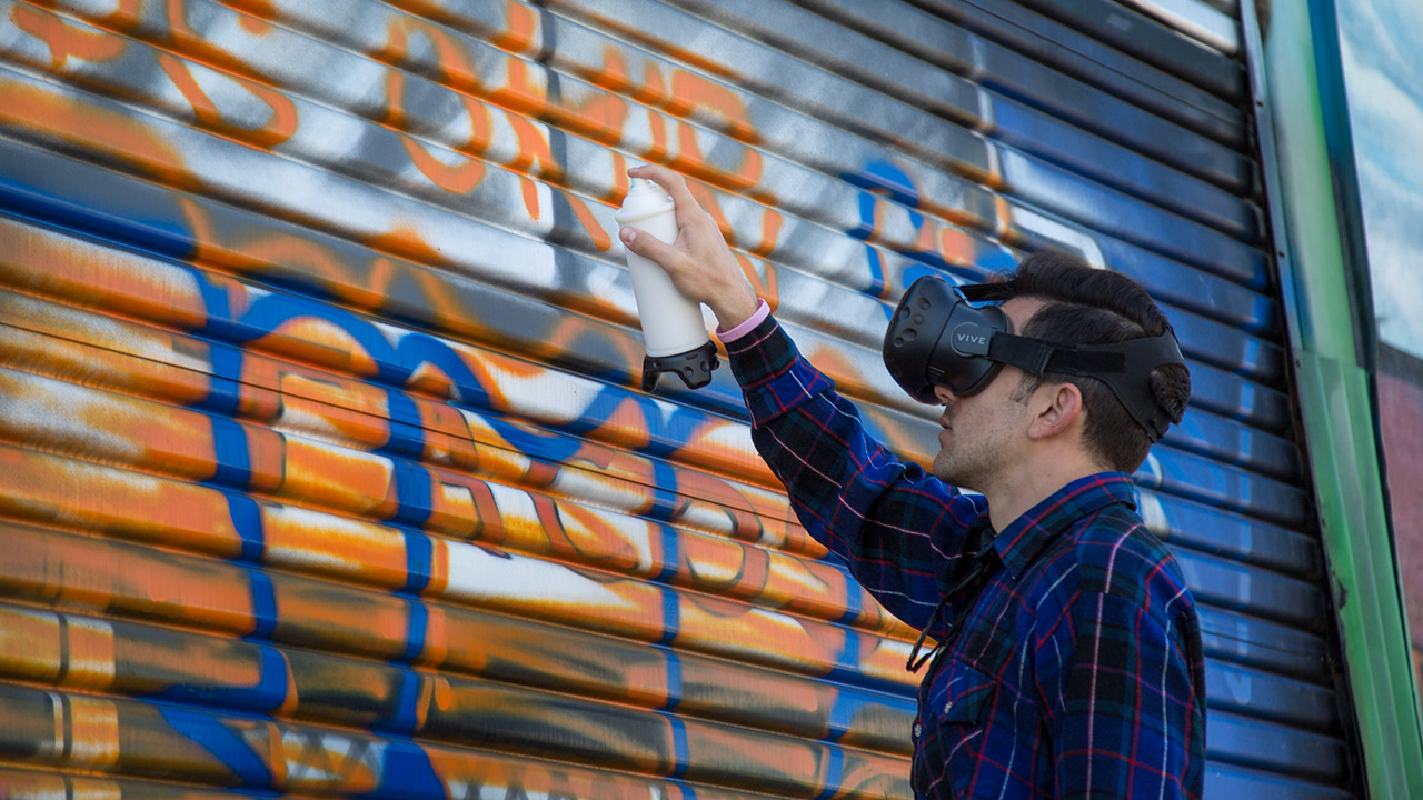
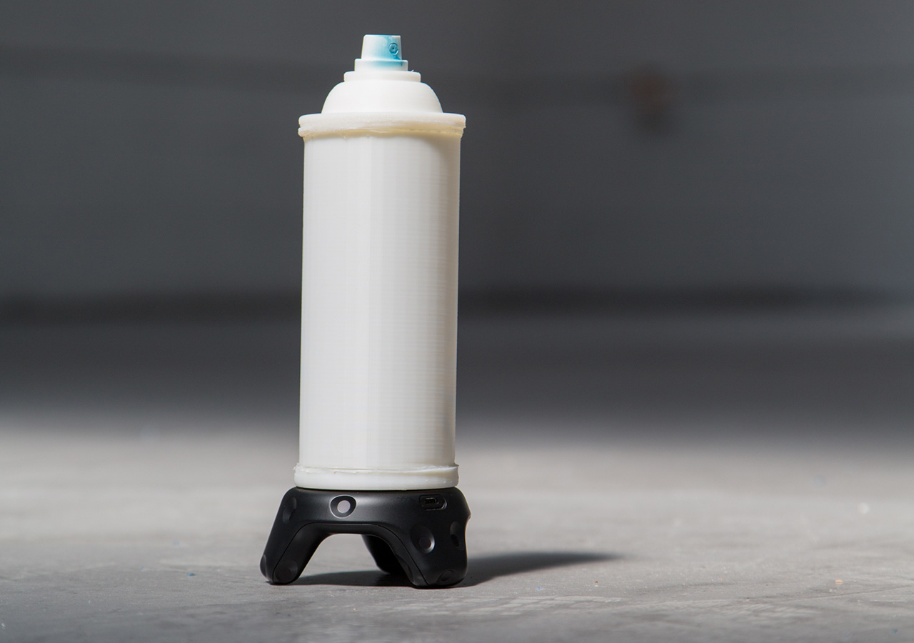
After working on the first-person-shooter-oriented Mobile Room-Scale, we wanted to make show off the more creative side of VIVE Tracker. For this, we developed a 3D-printed spray paint can that uses the GPIO pins on the VIVE Tracker to send commands to a demo game we’ve created in UE4.
In this tutorial, we will teach you how we did it. We’ll give you the print files needed, walk you through assembling the physical model once it has finished printing, and show you how to connect the incoming signals from the VIVE Tracker Spray Can into the demo game in UE4.
Part 1: Making the Controller
What you’ll need:
Tools
- -3D Printer
- -Solder tools
- -Hot glue gun
- -Wire Cutters
- -Small flathead or other tiny pry tool
Parts List:
- -VIVE Tracker
- -¼ inch attachment for VIVE Tracker
- -Print files
- -spray nozzle/cap from spray paint can
- –Scale up and scale down buttons
- -trigger button
- –22 gauge UL wire – solid
- –jumper cables female-female
Step 1: Print the models
Print Files Folder
Step 2: Assemble the Can
Full Assemble Can Video
Steps:
- 1) Print the 3D files
- 2) Remove the plastic shield from one side of 6 of the jumper pins
- 3) Take the jumper you are going to use for the ground and cut off the other shield
- 4) Strip the head of that jumper
- 5) Cut 1.5 inches from 4 other jumpers, keeping the shield on one end
- 6) Strip those wires and solder them to the ground cable to make a 4:1 ground jumper
- 7) Insert one of the exposed heads of each of the 6 jumpers into each of the holeson the printed base
- 8) Make sure the metal head sticks out about 1mm
- 9) Use the hot glue gun to lay hot glue into the rectangle to hold the jumpers in place
- 10) Fix the jumper heads into the correct position as the hot glue dries
- 11) Use the 1/4 in attachment to fasten the base to the tracker
- 12) Solder 3 inch of lead red and black wire to the scale up and scale down buttons
- 13) Strip 1⁄2 inch from the other end of the wires
- 14) Feed them through the holes on the cylinder and hot glue the buttons into the grooves
- 15) Solder 2.5 inches of green and black lead wire to the trigger button and feed the wire down the top of the cap. Use hot glue to fill the hole available.
- 16) Feed the female sides of the jumper cables attached to the base through the tunnel on the cylinder
- 17) Once fed through you can plug the buttons in. The up button will go to pin 3, the trigger to pin 4, and the down button to pin 6.
- 18) Line up the tunnel to the opposite of the pins on the base
- 19) Align the notches, and twist the cylinder into place, locking it to the base
- 20) Align the notched on the cap to the cylinder, twist, and lock the cap in place
- 21) Take the nozzle from the spray can and push it onto the top button
Part 2: Making the Game
What you’ll need:
For this tutorial, you will need the FBX file for the entire spray can along with the project files for the game we are building. The game is already finished, and the blueprints have all been extensively commented to let you know why we’re doing what we’re doing.
Spray Can: FBX Model
Spray Can: UE4 Project Files
Preface:
Since the VIVE Tracker has just come out, some of the programs we are using haven’t quite caught up to fully incorporating their functionality as of this tutorial. As such, we have a few workarounds to hold you over in the meantime. Once everyone has updated to the OpenVR version that fully supports the Trackers these workarounds won’t be needed.
The first thing you will need to do is download and use the VIVE Tracker Role Changer (VTRC). As of this tutorial, version 0.8 was the newest. Here is the LINK. That allows us to use the GPIO pins as controls when sending to programs, like UE4, that have not updated to the new version of OpenVR just yet.
Here are a few things we think you should be looking out for while we wait for the update to OpenVR:
- -Pairing the Tracker as the second device before using the VTRC will result in the
controller inputs coming in on the wrong hands. Example: Tracker location shows up as
LEFT controller but is triggering RIGHT inputs. - -If, for unexplainable reasons, the Trackers stops registering in UE4, try to restart
SteamVR. In most cases this solved the issue (we believe it is not closing the secondary
data connection when the game closes) and we were able to get back up and running
quickly. - -If the Tracker still does not show up, rebooting your machine should do it.
- -The Trackpad input (pin 5) currently does not register in UE4 with OpenVR.
Step 1: Setting up UE4 for the Motion Controllers
Full Motion Control Setup Video
Steps:
- 1) Create pawn blueprint
- 2) Add scene component
- 3) Add a camera to the scene component
- 4) Add a motion controller component for the left controller to the camera component
- 5) Add any static mesh to the controller component (I’m using a box I scaled down)
- 6) Add another motion controller component for the spray can
- 7) Set that Motion Controller Hand to Right
- 8) Add a scene component to the spray can motion controller, this will be tracker
- 9) Add the spray can mesh and an arrow component so you can see the spray direction
- 10) I set the arrow’s Z position to 180 and Z rotation to 270, which is right at the location of the spray can’s tip
- 11) I set this scene component’s X location to -12 to compensate for the tracker’s size and overall feel in the game.
- 12) I also rotate the scene component Rotation X & Z to -90 because the spray can’s movement did not feel right.
Step 2: Create the Controls for the Inputs
Full Create Controls Video
This section is built to follow within the Project as there are many parts to its operation. Please open the project files for even more detail on this build out.
Below is a summary of what to look for within the Project files:
- – Open the VR Pawn blueprint
- -Go to the Event Graph
- -On event begin play the tracking origin and color for the cube on the second controller are set
- -On event tick we are getting the valid tracked device ID of the controller type, the Tracker should come in as a controller after using VTRC
- -Since we are always connecting the tracker first, we’ll get the first valid ID and set the world location and rotation of the scene1 root of the can mesh
- -The second valid ID will do the same for the color cube on the left motion controller
- -The trigger will be used to change the boolean for “spraying”
- -The grip button will increase the size of the nozzle
- -The menu button currently comes in as the shoulder event. We will use that to decrease the nozzle size
- -On event tick we are checking if the “spraying” boolean is true
- -If it is we call the function line trace/set wall and paint ref
Outside of VR
More fun can be had even outside of VR. For example combined with a projector you can have all the fun of graffiti without the fumes.
© 2025 MASTER OF SHAPES INC. ALL RIGHTS RESERVED.